


Please Leave Us A Message
Privacy statement: Your privacy is very important to Us. Our company promises not to disclose your personal information to any external company with out your explicit permission.

 June 01, 2019
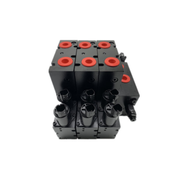
Due to the structural limitations of the fixed displacement, it is generally considered that the Gear Pump can only be used as a constant flow hydraulic source. However, the accessory-in-threaded combination valve solution is effective for improving its function, reducing system cost, and improving system reliability. Therefore, the performance of the gear pump can be close to the expensive and complicated plunger pump.
For example, installing a control valve directly on the pump eliminates the need for piping between the pump and the direction, thus controlling costs. Less pipe fittings and connectors reduce leakage and increase job reliability. Moreover, the pump itself can be installed with a valve to reduce the circulating pressure of the circuit and improve its working performance. Below are some of the circuits that improve the basic functions of Gear Pumps, some of which are basic circuits that have proven to be viable, while others are innovative.
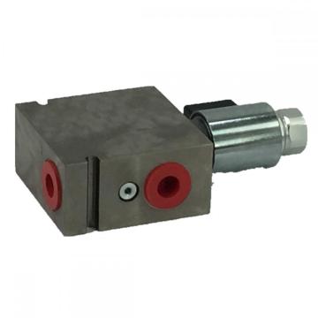
Unloading the circuit: The unloading element combines the high flow pump with the low power single pump. Liquid is discharged from the outlets of the two pumps to achieve a predetermined pressure and/or flow rate. At this point, the high flow pump circulates the flow from its outlet to the inlet, thereby reducing the pump's output flow to the system, ie reducing the magnetic power to a value slightly higher than the high pressure portion of the operation. The percentage of flow reduction depends on the ratio of undischarged displacement to total displacement at this time, and the combined or threaded unloading valve reduces or even eliminates piping, tunnels and accessories and other possible leaks.
The simplest unloading element is manually manipulated. The spring turns the unloading valve on or off. When the valve is actuated, the on/off state of the valve is switched. Lever or other mechanical mechanisms are the easiest way to manipulate such valves.
Pilot-controlled (pneumatic or hydraulic) unloading valves are an improvement in the way they are operated, as this allows the valve to be remotely controlled. The biggest advancement is the use of solenoid valves controlled electrically or electronically. Not only can it be remotely controlled, but it can also be automatically controlled by a microcomputer. It is generally considered that this simple unloading technique is the best case for the application. Manually operated unloading elements are often used in circuits that require high flow and fast operation for fast operation and require large flow and reduced flow for precise control, such as a fast-expanding boom circuit. Pressure sensing unloading is the most common solution. The spring action causes the unloading valve to be in its high flow position. When the circuit pressure reaches the preload value of the relief valve, the relief valve opens and the unloading valve switches to its small flow position under hydraulic pressure and action. The pressure sensing unloading valve is basically an automatic unloading element that reaches the system pressure and is unloaded, and is commonly used in odometer splitting and hydraulic vise.
The unloading valve in the flow sensing unloading circuit is also pressed by the spring to a high flow position. The fixed orifice size in the valve is determined by the flow rate required for the optimum engine speed of the equipment. If the engine speed exceeds this optimum range, the orifice orifice pressure drop will increase, shifting the unloading valve to the low flow position (right position). Therefore, the adjacent components of the large flow pump are made to be capable of throttling the maximum flow rate, so that the circuit has less energy consumption, stable operation, and lower cost. A typical application of such a loop is to limit the loop flow to an optimum range to improve the performance of the overall system or to limit the loop pressure during high speed travel of the machine. Often used in garbage trucks, etc. The unloading valve of the pressure flow sensing unloading circuit is also pressed by the spring to a large flow position and will be unloaded regardless of the predetermined pressure or flow rate. The equipment can perform high pressure operation at idle or normal working speed. This feature reduces unnecessary traffic and therefore reduces the power required. Because such circuits have a wide range of load and speed variations, they are commonly used in excavation equipment.
The above is the From the functional technology analysis, the gear pump must replace the plunger pump we have listed for you. You can submit the following form to obtain more industry information we provide for you.
You can visit our website or contact us, and we will provide the latest consultation and solutions
Send Inquiry
Most Popular
lastest New
Related Products
Send Inquiry
About Us
Related Products List
Contact Us

Send Inquiry
Privacy statement: Your privacy is very important to Us. Our company promises not to disclose your personal information to any external company with out your explicit permission.
Fill in more information so that we can get in touch with you faster
Privacy statement: Your privacy is very important to Us. Our company promises not to disclose your personal information to any external company with out your explicit permission.