


Please Leave Us A Message
Privacy statement: Your privacy is very important to Us. Our company promises not to disclose your personal information to any external company with out your explicit permission.

 July 30, 2019
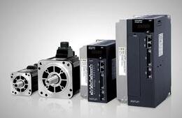
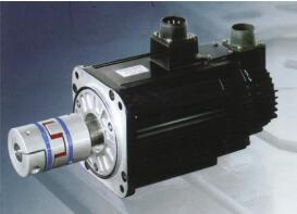
A servo motor is an engine that controls the operation of a mechanical component in a servo system, and is an auxiliary motor indirect transmission.
The servo motor can control the speed and position accuracy very accurately, and can convert the voltage signal into torque and speed to drive the control object. The servo motor rotor speed is controlled by the input signal and can react quickly. It is used as an actuator in the automatic control system, and has the characteristics of small electromechanical time constant, high linearity, and starting voltage, which can receive the received electrical signal. Converted to an angular displacement or angular velocity output on the motor shaft. Divided into two major categories of DC and AC servo motor, its main feature is that when the signal voltage is zero, there is no rotation phenomenon, and the rotation speed decreases uniformly with the increase of torque.
Simply put, for example, the electronic gear ratio is 1 (system default), the pulse equivalent is 1mm (that is, the distance the object runs when you send a pulse, note that the control pulse is the pulse that your PLC sends to the servo amplifier). When you change the electronic gear ratio to 2, the corresponding pulse equivalent becomes 2mm.
It can also be understood that you give the servo amplifier a pulse. When the electronic gear ratio is 1, the servo amplifier operates according to one pulse. When the electronic gear ratio is 2, the servo amplifier operates according to 2 pulses. And so on!
Setting for the maximum motor speed
When the servo motor rotates, the speed performance is heavier than the precision performance, and it is desirable to fully express the motor speed performance; and when the rotation resolution is low. The following methods are recommended.
1) Conditions and requirements, assuming that the servo motor rotation speed to be set is 3000R/min, the number of pulses per encoder of the encoder is 8192pulse/rev
2) Calculation instructions
The pulse frequency is 8192 & TImes relative to 3000R/min; 3000/60=409 600HZ=409.6KHZ
When the pulse output of the controller can only be up to 100kHZ, the molecular part CMX and the denominator part CDV of the electronic gear ratio are first set to 1, and then the 10KHZ pulse is sent by the controller JOG to be the pulse frequency of the maximum speed of 1/10. At this time, the servo motor speed is
(10/409.6) & TImes; 3000≈73R/min
If the speed is not calculated, you can directly monitor the drive speed value, which should also be 73R/min.
3) Setting method
The desired speed of the 10KHZ pulse should be 3000/min, but it is actually 73r/min. To correct the actual speed to 300r/min, the electronic gear ratio must be modified.
73&TImes;CMZ/CDV=300(R/MIN)
Therefore, the CMX molecule can be set to 300 and the CDV denominator can be set to 73.
The speed of the controller's pulse output frequency is 100KHZs.
3000&TImes;[(300/73)×100000] /409600=3009R/MIN
In this example, all structural conditions are ignored, and the resolution of the transmission part must be considered in practical applications. If the variability is ignored, the product will not be used.
How to determine the electronic gear ratio of the servo motor1. Introduction of electronic gear ratio parameters
The so-called "electronic gear" function has two main applications: one is to adjust the number of command pulses required to rotate the motor one turn to ensure that the motor speed can reach the required speed. For example, the maximum transmission pulse frequency of the host computer PLC is 200KHz. If the electronic gear ratio is not modified, the motor needs 10,000 pulses for one rotation, then the maximum motor speed is 1200 rpm. If the electronic gear ratio is set to 2:1, or every revolution When the number of pulses is set to 5000, the motor can reach 2400 rpm.
For example, the electronic gear ratio is set to 1:1 or the number of pulses per revolution is set to 10000, and the highest transmission pulse frequency of the upper computer PLC is 200KHz.
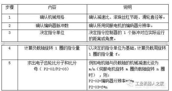
2. Calculation of the number of pulses per revolution and the ratio of electronic gears
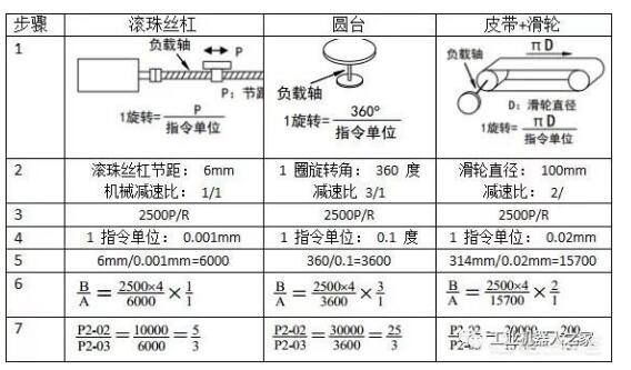
The number of pulses per revolution or the electronic gear ratio is calculated in the following order of 1 to 6.
note:
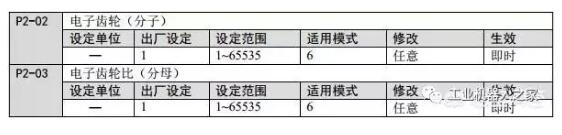
(1) The number of pulses per revolution and the electronic gear ratio can limit the amount of command required for the servo motor to rotate one revolution. The two are complementary, but the priority per pulse is higher than the electronic gear ratio, only the pulse per revolution. The electronic gear ratio will only take effect if the number is set to 0. This is something the user needs to pay attention to. In special cases, if the number of pulses per revolution is calculated as a decimal, the electronic gear ratio should be considered.
(2) When P2-02 and P2-03 exceed the setting range, set the numerator and denominator to an integer within the settable range. The difference in the case of not changing the ratio does not affect the use.
(3) The resolution of the motor encoder that is present without any special explanation is 2500P/R.
(4) The command unit does not represent machining accuracy. Refining the command unit amount on the basis of mechanical precision can improve the positioning accuracy of the servo. For example, when the lead screw is applied, the precision of the machine can reach 0.01 mm, so the command unit equivalent of 0.01 mm is more accurate than the command unit equivalent of 0.1 mm.
3. Setting examples of electronic gears
Example:
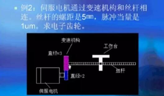
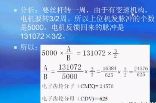
The supplementary explanation of the above example: the number of the upper machine pulse is 5000, the pass is, the screw pitch is 5mm, the pulse equivalent requirement is 0.001mm, so the number of pulses is 5/0.001=5000. The encoder feedback pulse is 131072 one revolution (servo motor), but due to the shifting mechanism, it is 3/2.
The above is the A text to understand the servo motor electronic gear ratio setting method we have listed for you. You can submit the following form to obtain more industry information we provide for you.
You can visit our website or contact us, and we will provide the latest consultation and solutions
Send Inquiry
Most Popular
lastest New
Send Inquiry
About Us
Related Products List
Contact Us

Send Inquiry
Privacy statement: Your privacy is very important to Us. Our company promises not to disclose your personal information to any external company with out your explicit permission.
Fill in more information so that we can get in touch with you faster
Privacy statement: Your privacy is very important to Us. Our company promises not to disclose your personal information to any external company with out your explicit permission.